WHAT IS SCR ?
SCR = Silicon-Controlled Rectifier
Shockley diodes are curious devices, but rather limited in application.
Their usefulness may be expanded, however, by equipping them with another
means of latching. In doing so, each becomes true amplifying devices (if
only in an on/off mode), and we refer to these as silicon-controlled
rectifiers, or SCRs. (The SCR Modules as: PRX SCR Module , Mitsubishi SCR Module , Sanrex SCR Module , Fuji SCR Module , Toshiba SCR Module , Fuji SCR Module , Siemens SCR Module , Eupec SCR Module , Semikron SCR Module , ABB SCR Module , PRX Silicon-Controlled Rectifier , Mitsubishi Silicon-Controlled Rectifier , Sanrex Silicon-Controlled Rectifier , Fuji Silicon-Controlled Rectifier , Toshiba Silicon-Controlled Rectifier , Fuji Silicon-Controlled Rectifier , Siemens Silicon-Controlled Rectifier , Eupec Silicon-Controlled Rectifier , Semikron Silicon-Controlled Rectifier , ABB Silicon-Controlled Rectifier )
The progression from Shockley diode to SCR is achieved with one
small addition, actually nothing more than a third wire connection to the
existing PNPN structure: (Figure below)
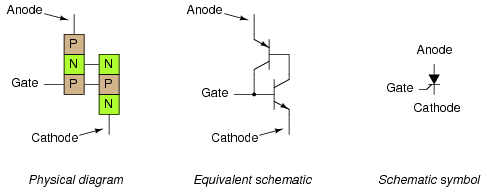
The Silicon-Controlled Rectifier (SCR)
If an SCR's gate is left floating (disconnected), it behaves exactly as a Shockley diode. It may be latched by
breakover voltage or by exceeding the critical rate of voltage rise between
anode and cathode, just as with the Shockley diode. Dropout is accomplished
by reducing current until one or both internal transistors fall into cutoff
mode, also like the Shockley diode. However, because the gate terminal
connects directly to the base of the lower transistor, it may be used as an
alternative means to latch the SCR. By applying
a small voltage between gate and cathode, the lower transistor will be
forced on by the resulting base current, which will cause the upper
transistor to conduct, which then supplies the lower transistor's base with
current so that it no longer needs to be activated by a gate voltage. The
necessary gate current to initiate latch-up, of course, will be much lower
than the current through the SCR from cathode
to anode, so the SCR does achieve a measure of
amplification.
This method of securing SCR conduction is
called triggering, and it is by far the most common way that SCRs are latched in actual practice. In fact, SCRs are usually chosen so that their breakover voltage
is far beyond the greatest voltage expected to be experienced from the power
source, so that it can be turned on only by an intentional voltage
pulse applied to the gate.
It should be mentioned that SCRs may sometimes be turned off by
directly shorting their gate and cathode terminals together, or by
"reverse-triggering" the gate with a negative voltage (in
reference to the cathode), so that the lower transistor is forced into
cutoff. I say this is "sometimes" possible because it involves
shunting all of the upper transistor's collector current past the lower
transistor's base. This current may be substantial, making triggered
shut-off of an SCR difficult at best. A variation of the SCR,
called a Gate-Turn-Off thyristor , or GTO,
makes this task easier. But even with a GTO, the gate current required to
turn it off may be as much as 20% of the anode (load) current! The schematic
symbol for a GTO is shown in the following illustration: (Figure below)
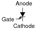
The Gate Turn-Off thyristor (GTO)
SCRs and GTOs share the same equivalent schematics (two transistors
connected in a positive-feedback fashion), the only differences being
details of construction designed to grant the NPN transistor a greater ?
than the PNP. This allows a smaller gate current (forward or reverse) to
exert a greater degree of control over conduction from cathode to anode,
with the PNP transistor's latched state being more dependent upon the NPN's
than vice versa. The Gate-Turn-Off thyristor is also known by the name of Gate-Controlled
Switch, or GCS.
A rudimentary test of SCR function, or at least terminal identification,
may be performed with an ohmmeter. Because the internal connection between
gate and cathode is a single PN junction, a meter should indicate continuity
between these terminals with the red test lead on the gate and the black
test lead on the cathode like this: (Figure below)
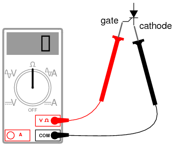
Rudimentary test of SCR
All other continuity measurements performed on an SCR will show
"open" ("OL" on some digital multimeter displays). It
must be understood that this test is very crude and does not constitute a comprehensive assessment of the SCR. It is possible for an SCR
to give good ohmmeter indications and still be defective. Ultimately, the
only way to test an SCR is to subject it to a load current.
If you are using a multimeter with a "diode check" function,
the gate-to-cathode junction voltage indication you get may or may not
correspond to what's expected of a silicon PN junction (approximately 0.7
volts). In some cases, you will read a much lower junction voltage: mere
hundredths of a volt. This is due to an internal resistor connected between
the gate and cathode incorporated within some SCRs. This resistor is added
to make the SCR less susceptible to false triggering by spurious
voltage spikes, from circuit "noise" or from static electric
discharge. In other words, having a resistor connected across the
gate-cathode junction requires that a strong triggering signal
(substantial current) be applied to latch the SCR. This feature is often
found in larger SCRs, not on small SCRs. Bear in mind that an SCR with an internal resistor connected between gate
and cathode will indicate continuity in both directions between those
two terminals: (Figure below)
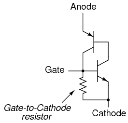
Larger SCRs have gate to cathode resistor.
"Normal" SCRs, lacking this internal resistor, are sometimes
referred to as sensitive gate SCRs due to their ability to be
triggered by the slightest positive gate signal.
The test circuit for an SCR is both practical as a diagnostic tool for
checking suspected SCRs and also an excellent aid to understanding basic SCR
operation. A DC voltage source is used for powering the circuit, and two
pushbutton switches are used to latch and unlatch the SCR, respectively:
(Figure below)
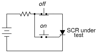
SCR testing circuit
Actuating the normally-open "on" pushbutton switch connects the
gate to the anode, allowing current from the negative terminal of the
battery, through the cathode-gate PN junction, through the switch, through
the load resistor, and back to the battery. This gate current should force
the SCR to latch on, allowing current to go directly from cathode to anode
without further triggering through the gate. When the "on"
pushbutton is released, the load should remain energized.
Pushing the normally-closed "off" pushbutton switch breaks the
circuit, forcing current through the SCR to halt, thus forcing it to
turn off (low-current dropout).
If the SCR fails to latch, the problem may be with the load and
not the SCR. A certain minimum amount of load current is required to
hold the SCR latched in the "on" state. This minimum
current level is called the holding current. A load with too great a
resistance value may not draw enough current to keep an SCR latched
when gate current ceases, thus giving the false impression of a bad (unlatchable) SCR in the test circuit. Holding current values for different SCRs
should be available from the manufacturers. Typical holding current values
range from 1 milliamp to 50 milliamps or more for larger units.
For the test to be fully comprehensive, more than the triggering action
needs to be tested. The forward breakover voltage limit of the SCR could be
tested by increasing the DC voltage supply (with no pushbuttons actuated)
until the SCR latches all on its own. Beware that a breakover test
may require very high voltage: many power SCRs have breakover voltage
ratings of 600 volts or more! Also, if a pulse voltage generator is
available, the critical rate of voltage rise for the SCR could be
tested in the same way: subject it to pulsing supply voltages of different
V/time rates with no pushbutton switches actuated and see when it latches.
In this simple form, the SCR test circuit could suffice as a
start/stop control circuit for a DC motor, lamp, or other practical load:
(Figure below)
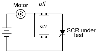
DC motor start/stop control circuit
Another practical use for the SCR in a DC circuit is as a crowbar device for overvoltage protection. A "crowbar" circuit consists of
an SCR placed in parallel with the output of a DC power supply, for
placing a direct short-circuit on the output of that supply to prevent
excessive voltage from reaching the load. Damage to the SCR and power
supply is prevented by the judicious placement of a fuse or substantial
series resistance ahead of the SCR to limit short-circuit current:
(Figure below)
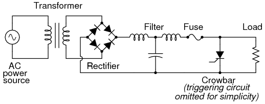
Crowbar circuit used in DC power supply
Some device or circuit sensing the output voltage will be connected to
the gate of the SCR, so that when an overvoltage condition occurs, voltage
will be applied between the gate and cathode, triggering the SCR and forcing
the fuse to blow. The effect will be approximately the same as dropping a
solid steel crowbar directly across the output terminals of the power
supply, hence the name of the circuit.
Most applications of the SCR are for AC power control, despite the fact
that SCRs are inherently DC (unidirectional) devices. If bidirectional
circuit current is required, multiple SCRs may be used, with one or more
facing each direction to handle current through both half-cycles of the AC
wave. The primary reason SCRs are used at all for AC power control
applications is the unique response of a thyristor to an alternating
current. As we saw, the thyratron tube (the electron tube version of the SCR)
and the DIAC, a hysteretic device triggered on during a portion of an AC
half-cycle will latch and remain on throughout the remainder of the
half-cycle until the AC current decreases to zero, as it must to begin the
next half-cycle. Just prior to the zero-crossover point of the current
waveform, the thyristor will turn off due to insufficient current (this
behavior is also known as natural commutation) and must be fired
again during the next cycle. The result is a circuit current equivalent to a
"chopped up" sine wave. For review, here is the graph of a DIAC's
response to an AC voltage whose peak exceeds the breakover voltage of the
DIAC: (Figure below)
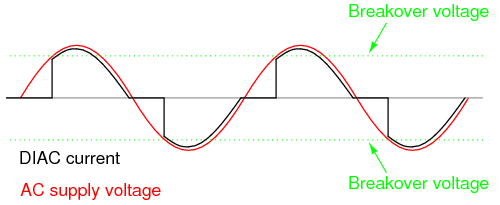
DIAC bidirectional response
With the DIAC, that breakover voltage limit was a fixed quantity. With
the SCR, we have control over exactly when the device becomes latched by
triggering the gate at any point in time along the waveform. By connecting a
suitable control circuit to the gate of an SCR, we can "chop" the
sine wave at any point to allow for time-proportioned power control to a
load.
Take the circuit in Figure below as an example. Here, an SCR is
positioned in a circuit to control power to a load from an AC source.
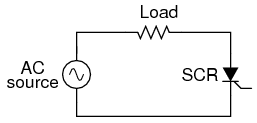
SCR control of AC power
Being a unidirectional (one-way) device, at most we can only deliver
half-wave power to the load, in the half-cycle of AC where the supply
voltage polarity is positive on the top and negative on the bottom. However,
for demonstrating the basic concept of time-proportional control, this
simple circuit is better than one controlling full-wave power (which would
require two SCRs).
With no triggering to the gate, and the AC source voltage well below the
SCR's breakover voltage rating, the SCR will never turn on. Connecting the
SCR gate to the anode through a standard rectifying diode (to prevent
reverse current through the gate in the event of the SCR containing a
built-in gate-cathode resistor), will allow the SCR to be triggered almost
immediately at the beginning of every positive half-cycle: (Figure below)
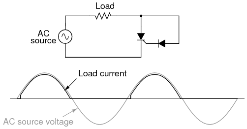
Gate connected directly to anode through a diode; nearly complete
half-wave current through load.
We can delay the triggering of the SCR, however, by inserting some
resistance into the gate circuit, thus increasing the amount of voltage drop
required before enough gate current triggers the SCR. In other words, if we
make it harder for electrons to flow through the gate by adding a
resistance, the AC voltage will have to reach a higher point in its cycle
before there will be enough gate current to turn the SCR on. The result is
in Figure below.
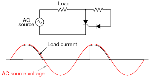
Resistance inserted in gate circuit; less than half-wave current
through load.
With the half-sine wave chopped up to a greater degree by delayed
triggering of the SCR, the load receives less average power (power is
delivered for less time throughout a cycle). By making the series gate
resistor variable, we can make adjustments to the time-proportioned power:
(Figure below)
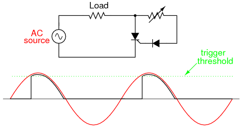
Increasing the resistance raises the threshold level, causing less
power to be delivered to the load. Decreasing the resistance lowers the
threshold level, causing more power to be delivered to the load.
Unfortunately, this control scheme has a significant limitation. In using
the AC source waveform for our SCR triggering signal, we limit control to
the first half of the waveform's half-cycle. In other words, it is not
possible for us to wait until after the wave's peak to trigger the
SCR. This means we can turn down the power only to the point where the SCR
turns on at the very peak of the wave: (Figure below)
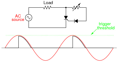
Circuit at minimum power setting
Raising the trigger threshold any more will cause the circuit to not
trigger at all, since not even the peak of the AC power voltage will be
enough to trigger the SCR. The result will be no power to the load.
An ingenious solution to this control dilemma is found in the addition of
a phase-shifting capacitor to the circuit: (Figure below)
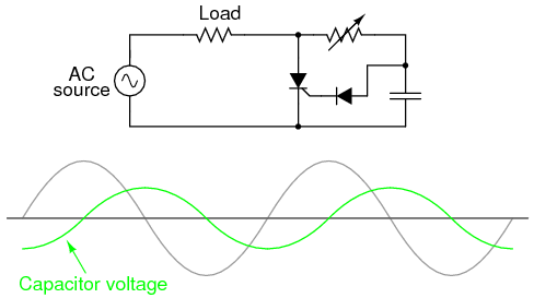
Addition of a phase-shifting capacitor to the circuit
The smaller waveform shown on the graph is voltage across the capacitor.
For the sake of illustrating the phase shift, I'm assuming a condition of
maximum control resistance where the SCR is not triggering at all with no
load current, save for what little current goes through the control resistor
and capacitor. This capacitor voltage will be phase-shifted anywhere from 0o to 90o lagging behind the power source AC waveform. When this
phase-shifted voltage reaches a high enough level, the SCR will trigger.
With enough voltage across the capacitor to periodically trigger the SCR,
the resulting load current waveform will look something like Figure below)
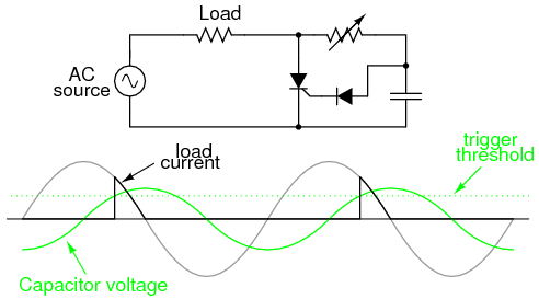
Phase-shifted signal triggers SCR into conduction.
Because the capacitor waveform is still rising after the main AC
power waveform has reached its peak, it becomes possible to trigger the SCR
at a threshold level beyond that peak, thus chopping the load current wave
further than it was possible with the simpler circuit. In reality, the
capacitor voltage waveform is a bit more complex that what is shown here,
its sinusoidal shape distorted every time the SCR latches on. However, what
I'm trying to illustrate here is the delayed triggering action gained with
the phase-shifting RC network; thus, a simplified, undistorted waveform
serves the purpose well.
SCRs may also be triggered, or "fired," by more complex
circuits. While the circuit previously shown is sufficient for a simple
application like a lamp control, large industrial motor controls often rely
on more sophisticated triggering methods. Sometimes, pulse transformers are
used to couple a triggering circuit to the gate and cathode of an SCR to
provide electrical isolation between the triggering and power circuits:
(Figure below)
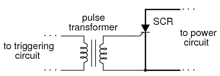
Transformer coupling of trigger signal provides isolation.
When multiple SCRs are used to control power, their cathodes are often not electrically common, making it difficult to connect a single triggering
circuit to all SCRs equally. An example of this is the controlled bridge
rectifier shown in Figure below.
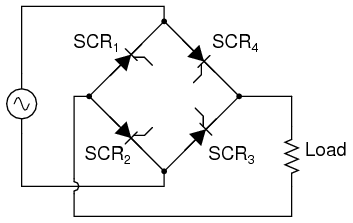
Controlled bridge rectifier
In any bridge rectifier circuit, the rectifying diodes (in this example,
the rectifying SCRs) must conduct in opposite pairs. SCR1 and SCR3 must be fired simultaneously, and SCR2 and SCR4 must
be fired together as a pair. As you will notice, though, these pairs of SCRs
do not share the same cathode connections, meaning that it would not work to
simply parallel their respective gate connections and connect a single
voltage source to trigger both: (Figure below)
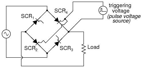
This strategy will not work for triggering SCR2 and SCR4 as a pair.
Although the triggering voltage source shown will trigger SCR4,
it will not trigger SCR2 properly because the two thyristors do
not share a common cathode connection to reference that triggering voltage.
Pulse transformers connecting the two thyristor gates to a common triggering
voltage source will work, however: (Figure below)

Transformer coupling of the gates allows triggering of SCR2 and SCR4 .
Bear in mind that this circuit only shows the gate connections for two
out of the four SCRs. Pulse transformers and triggering sources for SCR1 and SCR3, as well as the details of the pulse sources themselves,
have been omitted for the sake of simplicity.
Controlled bridge rectifiers are not limited to single-phase designs. In
most industrial control systems, AC power is available in three-phase form
for maximum efficiency, and solid-state control circuits are built to take
advantage of that. A three-phase controlled rectifier circuit built with
SCRs, without pulse transformers or triggering circuitry shown, would look
like Figure below.
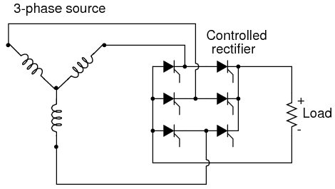
Three-phase bridge SCR control of load
- REVIEW:
- A Silicon-Controlled Rectifier, or SCR, is essentially a
Shockley diode with an extra terminal added. This extra terminal is
called the gate, and it is used to trigger the device into
conduction (latch it) by the application of a small voltage.
- To trigger, or fire, an SCR, voltage must be applied between
the gate and cathode, positive to the gate and negative to the cathode.
When testing an SCR, a momentary connection between the gate and anode
is sufficient in polarity, intensity, and duration to trigger it.
- SCRs may be fired by intentional triggering of the gate terminal,
excessive voltage (breakdown) between anode and cathode, or excessive
rate of voltage rise between anode and cathode. SCRs may be turned off
by anode current falling below the holding current value (low-current dropout), or by "reverse-firing" the gate
(applying a negative voltage to the gate). Reverse-firing is only
sometimes effective, and always involves high gate current.
- A variant of the SCR, called a Gate-Turn-Off thyristor (GTO), is
specifically designed to be turned off by means of reverse triggering.
Even then, reverse triggering requires fairly high current: typically
20% of the anode current.
- SCR terminals may be identified by a continuity meter: the only two
terminals showing any continuity between them at all should be the gate
and cathode. Gate and cathode terminals connect to a PN junction inside
the SCR, so a continuity meter should obtain a diode-like reading
between these two terminals with the red (+) lead on the gate and the
black (-) lead on the cathode. Beware, though, that some large SCRs have
an internal resistor connected between gate and cathode, which will
affect any continuity readings taken by a meter.
- SCRs are true rectifiers: they only allow current through them
in one direction. This means they cannot be used alone for full-wave AC
power control.
- If the diodes in a rectifier circuit are replaced by SCRs, you have
the makings of a controlled rectifier circuit, whereby DC power
to a load may be time-proportioned by triggering the SCRs at different
points along the AC power waveform.
|