What is Field-effect-controlled thyristors ?
Two relatively recent technologies designed to reduce the
"driving" (gate trigger current) requirements of classic thyristor devices are the MOS-gated thyristor and the MOS Controlled Thyristor, or MCT. (Parts as PRX Thyristor , Mitsubishi Thyristor , Sanrex
Thyristor , Fuji Thyristor , Toshiba
Thyristor , Fuji Thyristor , Siemens
Thyristor , Eupec Thyristor , Semikron Thyristor , ABB Thyristor )
The MOS-gated thyristor uses a MOSFET to initiate conduction through the
upper (PNP) transistor of a standard thyristor structure, thus triggering
the device. Since a MOSFET requires negligible current to "drive"
(cause it to saturate), this makes the thyristor as a whole very easy to
trigger: (Figure below)
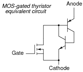
MOS-gated thyristor equivalent circuit
Given the fact that ordinary SCRs are quite easy to "drive" as
it is, the practical advantage of using an even more sensitive device (a
MOSFET) to initiate triggering is debatable. Also, placing a MOSFET at the
gate input of the thyristor now makes it impossible to turn it off by
a reverse-triggering signal. Only low-current dropout can make this device
stop conducting after it has been latched.
A device of arguably greater value would be a fully-controllable
thyristor, whereby a small gate signal could both trigger the thyristor and
force it to turn off. Such a device does exist, and it is called the MOS
Controlled Thyristor, or MCT. It uses a pair of MOSFETs connected
to a common gate terminal, one to trigger the thyristor and the other to
"untrigger" it: (Figure below)
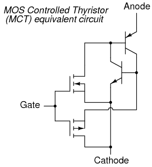
MOS-controlled thyristor (MCT) equivalent circuit
A positive gate voltage (with respect to the cathode) turns on the upper
(N-channel) MOSFET, allowing base current through the upper (PNP)
transistor, which latches the transistor pair in an "on" state.
Once both transistors are fully latched, there will be little voltage
dropped between anode and cathode, and the thyristor will remain latched as
long as the controlled current exceeds the minimum (holding) current value.
However, if a negative gate voltage is applied (with respect to the anode,
which is at nearly the same voltage as the cathode in the latched state),
the lower MOSFET will turn on and "short" between the lower (NPN)
transistor's base and emitter terminals, thus forcing it into cutoff. Once
the NPN transistor cuts off, the PNP transistor will drop out of conduction,
and the whole thyristor turns off. Gate voltage has full control over
conduction through the MCT: to turn it on and to turn it off.
This device is still a thyristor, though. If zero voltage is applied
between gate and cathode, neither MOSFET will turn on. Consequently, the
bipolar transistor pair will remain in whatever state it was last in (hysteresis).
So, a brief positive pulse to the gate turns the MCT on, a brief negative
pulse forces it off, and no applied gate voltage lets it remain in whatever
state it is already in. In essence, the MCT is a latching version of the
IGBT (Insulated Gate Bipolar Transistor).
- REVIEW:
- A MOS-gated thyristor uses an N-channel MOSFET to trigger a
thyristor, resulting in an extremely low gate current requirement.
- A MOS Controlled Thyristor, or MCT, uses two MOSFETS to
exert full control over the thyristor. A positive gate voltage triggers
the device; a negative gate voltage forces it to turn off. Zero gate
voltage allows the thyristor to remain in whatever state it was
previously in (off, or latched on).
|